Introduction
Healthcare has been a global concern that consistently captures widespread attention1,2,3. According to the facts from the World Health Organization (WHO), cardiovascular disease (CVD), the leading cause of death globally, caused 17.9 million deaths in 2019 (32% of global deaths)4, while cancers accounted for nearly 10 million deaths, nearly one in six deaths5. Many other diseases, such as diabetes6, hypertension7, heart attack8, and epilepsy9, are also causing negative health and premature death. As a result, a crucial shift from reactive to holistic and preventative healthcare is needed, and public health expenditures should be reduced to make healthcare resources more universally accessible10. Therefore, proactively detecting bioelectric signals is necessary and should be implemented in a low-power, low-cost, reliable, and convenient manner to facilitate early disease diagnosis11. With advances in material science and integrated circuits, biosensors, the devices to detect, process, and analyze biosignals, have been gaining great popularity in both research and daily life12.
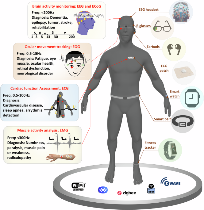
A biosensor typically comprises a bio-receptor, a transducer (which converts a biological response into an electric signal), and an electronic system (generally composed of amplifiers, filters, and data acquisition devices)13,14. Embarking on the third generation with significantly higher electron transfer efficiency and sensitivity15, the evolution of biosensors has been propelled by multi-disciplinary research16, heading towards low power, battery-less, excellent reliability, and minimal disruption to users’ daily life. Moreover, an increasing number of biosensors are being interconnected with traditional radio frequency (RF) communications and integrated into a wearable device (e.g., E-glasses17, smartwatches18, vests19, belts20), forming an Internet of Bodies (IoB) system to provide more comprehensive real-time healthcare, as shown in Fig. 1. These make the strategic design of biosensor circuits a critical focus, enabling efficient detection and processing of biosignals. Numerous factors must be considered in biosensor design, including electrode, input impedance, gain, bandwidth, power consumption, noise, interference, motion artifacts, and direct current (DC) offset. Extensive studies have been implemented in this field21,22,23,24, leading to numerous bioelectric signal sensor designs with various specifications, use scenarios (wearable, implantable, injectable, ingestible, etc.), and strategies to address the aforementioned challenges.

The left side of the figure sequentially introduces biosignals for monitoring brain activity (EEG/ECoG), tracking ocular movements (EOG), measuring cardiac function (ECG), and capturing muscle activity (EMG), each with their respective diagnostic functions based on the physiological signal type. The biosensors are being interconnected by radio frequency communications, as depicted at the bottom of the figure, such as Bluetooth and ZigBee. These sensors are integrated into miniaturized smart wearable devices, displayed on the right side, enabling continuous and real-time health monitoring. EEG electroencephalogram, ECoG electrocorticogram, ECG electrocardiogram, EOG electrooculogram, EMG electromyogram.
The existing reviews have thoroughly explored the electrodes, fabrication, materials, mechanisms, and applications of various types of biosensors25,26,27,28,29. However, there is a salient gap in the literature regarding the design considerations of biosensor circuits. Moreover, an in-depth discussion on the strategies to address design problems in response to these considerations is absent. This paper exhaustively reviews the design considerations, strategies, challenges, and insights of circuit design for biosensors used in detecting bioelectric signals, including electroencephalogram (EEG), electrocorticogram (ECoG), electrocardiogram (ECG), electrooculogram (EOG), and electromyogram (EMG), to bridge this gap. Specifically, we address the following topics:
-
The biosensor circuits to acquire and process bioelectric signals are overviewed. The strategies adopted by the biosensors to address various design issues are summarized.
-
Design considerations and challenges of biosensor circuits are analyzed, and the strategies to address these considerations and challenges are elucidated.
-
The commercial off-the-shelf (COTS) components as the analog front end (AFE) for biomedical signal acquisition and preprocessing are reviewed. Moreover, the commercial consumer wearables for home-based preventive care are examined. The key performances of COTS components and consumer wearables are discussed and compared.
-
Emerging and high–impact research areas that are either driving or benefiting from advancements in biosensor technologies are discussed.
Bioelectric signal overview
Bioelectric signals originate from the physiological activity of organs such as the brain, heart, eyes, and skeletal muscles30. However, these signals are typically low in amplitude, susceptible to various noises, and exhibit diverse temporal and spectral characteristics. The design of biosensing circuits for their acquisition and analysis requires a detailed understanding of their biophysical origins, signal features, and application-specific demands.
Brain activity monitoring: EEG and ECoG
EEG has emerged as a transformative technology for real-time brain-computer interfaces, enabling direct neural control of external devices and paving the way for assistive communication and neuroprosthetic systems. Besides, EEG remains the clinical gold standard for sleep staging and long-term epilepsy monitoring, and supports brain-machine interfaces (BMIs)31. EEG signals are generated by the postsynaptic potentials of well-aligned pyramidal neurons, producing detectable electrical activities32. Recorded non-invasively via scalp electrodes, these signals represent the aggregate extracellular ionic currents produced by neurons, and reflect the brain’s electrophysiological state, activities, and emotions33. Typically, EEG signals exhibit peak-to-peak amplitudes of 10–100 μV, with five rhythms (δ, θ, α, β, γ waves), predominantly below 100 Hz. However, EEG inherently offers limited spatial and temporal resolution because neural activity is attenuated and spatially smeared as it propagates through the skull and scalp.
ECoG provides a higher-fidelity alternative to EEG and is a critical tool in neurosurgery, functional cortical mapping, and advanced BMI research. With electrodes placed directly on the cortical surface, ECoG bypasses skull-induced attenuation and offers higher signal amplitudes (0.1–5 mV), improved spatial resolution, and is effective in capturing high-frequency γ band, which is essential for cognitive, motor, and language functions34. Nevertheless, ECoG is inherently invasive and requires craniotomy. Long-term recordings are challenged by tissue responses such as inflammation, gliosis, and fibrosis, which gradually increase electrode-tissue impedance and degrade signal quality over time. To enhance the spatial and temporal resolutions, EEG and ECoG sensors typically adopt a multi-channel architecture with high-density electrode arrays. Each channel requires a high input impedance, low-noise instrumentation amplifiers (IA), filtering, and robust common-mode rejection to ensure signal integrity and minimize artifacts. Compared with functional magnetic resonance imaging (fMRI), which infers neural activity indirectly through changes in cerebral blood flow, EEG and ECoG capture deliver millisecond-level temporal resolution for brain activity monitoring. Magnetoencephalography (MEG) offers similar precision but demands magnetically shielded environments, limiting portability. Thus, EEG and ECoG remain the most practical modalities for real-time cortical monitoring.
Cardiac function assessment: ECG
ECG is indispensable for continuous cardiac monitoring in wearable health systems, enabling early detection of life-threatening arrhythmias, ischemia, and real-time assessment of cardiovascular health. ECG signals originate from electrical activity caused by depolarization and repolarization of the heart muscle during rhythmic contractions35. The ECG signal typically spans 0.05–100 Hz, with a peak-to-peak amplitude range of 0.1–10 mV, and contains rich temporal and morphological features represented by wave components, including P wave, PR segment, QRS complex, ST segment, T wave, and U wave. Certain applications, for instance, pacemaker high-frequency spike detection, demand an extended bandwidth that requires acquisition well beyond 100 Hz to ensure accurate monitoring36. Though relatively high in amplitude, ECG signals are susceptible to motion artifacts caused by skin deformation and body movements. The complexity of removing motion artifacts arises from the spectral overlap between physiological motion (<10 Hz) and the low-frequency components of the ECG (such as the P-wave and T-wave). Therefore, ECG biosensing circuits typically incorporate high common-mode rejection ratio (CMRR) IA, bandpass and notch filters, and right-leg drive (RLD) circuits. Furthermore. ECG waveform spans a wide dynamic range, necessitating highly linear amplification to prevent saturation or clipping, particularly during high-amplitude QRS events. Aside from ECG, cardiac activity can also be assessed using photoplethysmography (PPG), or phonocardiography (PCG). However, these modalities can only indirectly estimate cardaic function through pulse rate, while ECG offers definitive diagnostic capability and enables cardiac abnormalities analysis with millisecond temporal precision, which is crucial for accurate and timely cardiac monitoring.
Ocular movement tracking: EOG
EOG is widely used in clinical diagnosis, sleep and anesthesia monitoring, affective computing, and assistive technologies for communication and control37 The human eyes behave as a dipole formed by the cornea (positive) and retina (negative)38. EOG signals are generated by the corneo-retinal dipole potential variations during eye movements and detected by electrodes placed around the eyes39. The EOG signal typically occupies the 0.5–15 Hz band, with peak-to-peak amplitudes below 2 mV. Even subtle gaze shifts on the order of one degree can produce detectable voltage changes of 5–20 μV40. However, EOG acquisition is challenged by a large DC component on the order of hundreds of millivolts, and baseline drift caused by ambient light, metabolic changes, and skin impedance. These factors complicate distinguishing true gaze shifts from slow signal drift. Therefore, EOG acquisition circuits must balance sensitivity to microvolt-level changes with robustness to large DC offsets. This requires high-precision DC-stable amplifiers, high common-mode rejection, drift compensation, and digital processing to ensure reliable performance in both clinical and interactive applications. Despite these challenges, unlike camera-based or infrared eye-tracking systems, which require illumination and fail with closed eyelids, EOG operates independently of visual conditions, enabling eye-tracking during sleep, anesthesia, and low-light environments. This resilience makes EOG indispensable for applications ranging from affective computing and sleep research to next-generation wearable interfaces, where robustness and adaptability are paramount.
Muscle activity analysis: EMG
EMG plays a pivotal role in advancing human augmentation and neurorehabilitation, enabling intuitive control of prosthetics, exoskeletons, and interactive human-machine interfaces. Its ability to decode neuromuscular intent in real time positions EMG as a key technology for assistive systems and performance analytics in both clinical and wearable domains41. EMG signals originate from motor neuron activation, causing motor unit action potentials (MUAPs), which are summed and propagated through muscle fibers42. Surface EMG (sEMG) signals typically span a peak-to-peak amplitude range of 10 μV to several mV and a frequency range of 10–300 Hz43. In comparison, intramuscular EMG (iEMG) signals exhibit a broader bandwidth extending to 1500 Hz and larger peak-to-peak amplitudes reaching up to 100 mV44,45. EMG signals are highly variable, transient, and strongly non-stationary, with amplitude and spectral content dynamically modulated by muscle contraction level and fatigue. Therefore, systems with high density and fast sampling are usually required to capture the complex temporal and spatial details of muscle activation46. Surface recordings face challenges, such as motion artifacts, fluctuations in electrode-skin impedance, cross-talk from adjacent muscles, and signal distortion caused by electrode shift, while subcutaneous fat layers further attenuate and blur the signal. Despite these limitations, EMG offers direct, high-fidelity access to neuromuscular activity at its electrical origin, outperforming alternative approaches such as imaging, mechanical sensors, and fMRI in portability, responsiveness, and real-time adaptability. These attributes make EMG indispensable for applications ranging from clinical diagnostics and rehabilitation robotics to wearable systems that seamlessly translate muscle intent into machine action.
Design considerations and challenges of biosensors
This section delves into the critical design considerations and challenges of biosensors, including impedance management, noise reduction, power efficiency, and energy harvesting techniques, to enhance performance and usability.
Impedances
Impedances play a critical role in biosensor front-end (FE) design as they determine how weak biopotential signals are transferred from the body to the electronic circuitry. Specifically, the human body acts as a bioelectric signal source. As illustrated in Fig. 2a, the measured electrode impedance on the skin Zt, which serves as the source impedance, includes the electrode impedance, the electrode-skin contact impedance, and the resistive and capacitive characteristics of skin and body tissues. When the bioelectric signal reaches the FE input, source impedance Zt interacts with the amplifier input impedance Rin and forms a voltage divider. As a result, the signal amplitude captured by the FE vin is given by ({v}_{in}={v}_{source}cdot frac{{R}_{in}}{{R}_{in}+{Z}_{t}}). Because of this voltage division effect, if the amplifier input impedance Rin is not sufficiently high relative to the source impedance Zt, a significant portion of the signal is lost across the source impedance Zt, leading to amplitude reduction and degraded signal fidelity. At the same time, high source impedance increases noise susceptibility and thermal noise. Overall, reducing source impedance while ensuring a sufficiently high amplifier input impedance is essential for achieving high-fidelity and low-noise biopotential acquisition.

a Illustration of impedances, including input impedance, output impedance, contact impedance, and electrode impedance47,57. VHC is the half-cell potential (electrode-electrolyte potential); CDL double-layer capacitance (charge accumulation across electrode-electrolyte interface); RCT is the charge transfer resistance; REL is the electrolyte layer resistance; Cair is the capacitance between the electrode and skin; CINT is the skin-electrode capacitance through insulation layer; Zc is the contact impedance; Vsc is the potential difference across the stratum corneum; Zs and Zbody are skin and body impedances; Zt is the measured electrode impedance on the skin, including electrode impedance, contact impedance, and skin and body impedances47. b Frequency and amplitude ranges of bioelectric signals and noises. Biosignals typically have very low frequencies and are affected by 1/f noise, thermal noise, and powerline noise. Evoked Potential (EP) is the electrical response of the nervous system to specific external stimuli. c Illustration of radio frequency interference (RF) on biosensor systems. RF interference from various sources, such as electronic devices, crosstalk, powerlines, and radio transmitters, can cause signal degradation, communication errors, and other issues that disrupt the functioning of biosensors.
Electrodes are generally classified into surface electrodes resting on the skin and implanted electrodes directly contacting body tissues and fluids. Surface electrodes include wet, semi-dry, dry contact, and dry capacitive types47. Wet electrodes (e.g., Ag/AgCl electrodes) use electrolytes to interface with the skin, which can be modeled as electrode-electrolyte potential VHC, charge transfer resistance RCT, double-layer capacitance CDL, and the electrolyte layer resistance REL (Fig. 2a). Their intrinsic impedance ranges from tens to hundreds of Ω48,49. Due to the conductive electrolyte between the electrode and skin, the electrode-skin impedance is the lowest, which is typically several to tens of kΩ50,51 measured up to 10 kHz. However, gel dehydration and long-term use can degrade performance and cause skin irritation. Semi-dry electrodes contain a built-in reservoir releasing electrolyte onto the skin upon contact. They operate similarly to wet electrodes, but with slightly higher impedance due to reduced electrolyte volume (Table 1). Compared with wet electrodes, they offer improved wearing comfort and are better suited for long-term use. Dry contact electrodes contact the skin without electrolytes, leading to substantially higher electrode-skin impedances (tens to hundreds of kΩ at 1 Hz to 10 kHz50,52) than wet electrodes. Dry capacitive electrodes, separated from the skin by a dielectric layer, exhibit even higher electrode-skin impedance up to several MΩ (Table 153,54). Dry electrodes are sensitive to motion artifacts, applied pressure, and gaps at the electrode-skin interface caused by sweat, dust, etc. However, they are ideal for long-term monitoring with superior wear comfort and reusability. Implanted electrodes, typically metallic microneedles or probes, provide direct signal access and are usually used for recording or stimulation. Stimulation electrodes deliver current to tissue and exhibit lower impedance (hundreds of Ω to several kΩ) than recording electrodes55,56.
The skin impedance is typically modeled as a parallel resistor-capacitor (RC) circuit characterized by a capacitance Cs and a resistance Rs47. Specifically, Cs represents the capacitive behavior of the thin and insulating layer of stratum corneum. It acts as a sandwiched dielectric between two conductive plates: the deep water-rich dermis and the sweat layer on the skin surface. Moreover, Rs is the resistive ion diffusion pathway between sweat glands and skin surface. Together, Rs and Cs describe the frequency-dependent nature of skin impedance: Rs creates parallel resistive shunts allowing DC and low-frequency currents to bypass the capacitive barrier, whereas Cs forms a significant capacitor dominating the impedance of the stratum corneum as a poor conductor at higher frequencies. Overall, at the FE amplifier, the input impedance Rin should be significantly higher than the source impedance Zt (Fig. 2a) to maximize the voltage captured by the FE amplifier. Moreover, a low output impedance Rout and a larger load impedance Rload are preferred to maximize voltage transfer to the load and subsequent circuit stages. Considerations are often taken to reduce Zt and boost the input impedance of the amplifier for more efficient detection of biosignals.
Reduce electrode impedance on the skin Zt
Reducing Zt can be done by reducing Zc, Zs or the electrode impedance. The electrode impedance is much smaller than the other two in state-of-the-art wet and dry electrodes, so it does not cause a major influence. The contact impedance Zc can be reduced by using wet electrode for short-term measurements with electrolyte to increase the conductivity of the skin, flexible or textile electrodes to increase the contact area with the skin, applying more pressure to the electrode, or using pin-shaped dry electrodes with micro-tips which can penetrate the hair and the epidermis and contact well with the skin57. Using motion-reduction devices, such as EEG caps or chest belts, is desirable to prevent the contact impedance variation caused by motions. The variation of contact impedance can be monitored with the time constant of the RC circuit58 and the received power after channel perturbation59, and compensated by adjustable gain amplifiers. The skin impedance Zs can be reduced by skin preparation by removing the non-conductive stratum corneum. It can also remove the hair to guarantee good skin-electrode contact.
Boost input impedance Rin
Employing FE with high input impedance ensures that the signal voltage drop occurs primarily across the amplifier input rather than the electrode-skin interface, which prevents signal loss due to voltage division. Additionally, high input impedance reduces the circuit’s sensitivity to source impedance variations. This is vital for improving CMRR, as it stops unequal electrode impedances from converting common-mode interference into differential noise, while also minimizing artifacts from motion-induced contact changes60. Several circuit design strategies are available to boost the input impedance of the FE. First, a buffer amplifier is a unity-gain amplifier that replicates the input signal at the output over a defined frequency range. It features a very high input impedance (hundreds of MΩ) and an ultra-low output impedance (on the order of Ω). Buffers or high input-impedance preamplifiers can be used following the electrode to convert the high Zt to low impedance, forming active electrodes57. Besides buffer amplifiers, pseudo-differential amplifiers with DC-coupled resistor-feedback, and cascode amplifiers also feature large input impedance (GΩ magnitude) and can be used for biosensing62.
Additionally, input impedances can be boosted by feedback loops and parasitic cancellations. Positive feedback loop (PFL), where the output current is fed back to the input to counteract the loading effect and reduce the input current, can boost the input impedance to 10 GΩ63. It can also be implemented with CCIA and achieves an input impedance of 30 MΩ64. However, the PFL needs to be carefully controlled and calibrated65 to make the feedback work effectively. The parasitic capacitors significantly degrade the input impedance by diverting the signal into ground through a low-impedance branch. To cancel the parasitics, negative capacitors can be generated by mimicking the behavior of a capacitor with a negative value to boost the input impedance to GΩ66,67. Additionally, the parasitic capacitances can be precharged at the input with auxiliary buffers to prevent the current from flowing through the input, resulting in a high input impedance of 1.6 GΩ68. These methods can be combined with the active shielding to directly mitigate the trace parasitics at the FE input, which further boosts the input impedance to tens of GΩ or even TΩ60,69.
Impedance monitoring and compensation
In order to address the challenges posed by varying human motions, postures, and environmental changes, impedance monitoring and compensation techniques have been developed in previous studies. These techniques focus on detecting and compensating for variable skin-electrode contact impedance, which can degrade signal fidelity. Saadeh et al.70 proposed an RC relaxed contact impedance monitor that utilizes different time constants obtained from various suspension distances between the electrode and the skin. A larger distance reduces the capacitance between skin and electrode, resulting in a shorter time constant and a faster rising and falling time of the signal. The different time constants are translated to different duty cycles by a variable-threshold limiter, which is recorded by a tracking counter. The gain of the front-end amplifier can be adjusted accordingly to compensate for the signal loss caused by varying contact impedance. Similarly, Jaeeun et al.59 introduced a contact impedance sensor that injects chopper-modulated current into the body and measures the voltage difference in electrode contact after amplification and demodulation, achieving reliable impedance coverage up to 1 kΩ. To overcome extra power consumption caused by active monitoring, passive monitoring techniques have been proposed, leveraging variations in amplifier output or environmental interference (e.g., line-frequency noise) as indirect indicators of contact quality, enabling continuous assessment without disturbing the recorded signals71. Compensation strategies include hardware solutions such as high-input-impedance amplifiers and active electrodes, which minimize the impact of poor contact by reducing current draw at the skin interface, as well as adaptive algorithms that dynamically adjust gain or trigger artifact rejection based on impedance trends.
1/f noise
In biosignal acquisition, a fundamental conflict exists between the bioelectric signal and the noise caused by the intrinsic physics of semiconductor devices. Bioelectric signals, such as EEG, ECG, etc., occupy very low-frequency bands, where MOSFETs exhibit their highest noise levels. Severe 1/f noise can significantly elevate the noise floor at these frequencies and effectively bury bioelectric signals, such as the EEG signal and the P-wave in ECG, due to their very low microvolt-level amplitude. 1/f noise, also known as flicker noise, has a power spectral density inversely proportional to frequency. In a single MOSFET, ({{rm{V}}}_{n,f}^{2}=frac{K}{{C}_{ox}WLf}), where Vn,f denotes flicker noise voltage, W and L are width and length of MOSFET, Cox the gate-oxide capacitance, K the process-dependent constant, and f is the frequency. As bioelectric signals typically occupy very low-frequency bands (Fig. 2b), they are highly susceptible to 1/f noise. Therefore, effective mitigation strategies are essential to preserve signal integrity.
Chopper stabilization is the most widely adopted technique for 1/f noise mitigation in bioelectric sensing systems72. The principle involves modulating low-frequency input signal (with both desired signal and 1/f noise) by multiplying it with a chopping signal. This shifts the signal spectrum to a higher frequency band beyond 1/f corner, where 1/f noise is negligible. After amplification and band-pass filtering, the signal is demodulated by multiplying with the same chopping wave, and high-frequency components are filtered, leaving clean bioelectric signal with 1/f noise removed72. Although highly effective, chopper stabilization significantly increases hardware complexity and can reduce input impedance by introducing parasitics57, necessitating input impedance boosting discussed earlier.
Compared with chopper stabilization, the correlated double sampling (CDS) technique has a lower hardware complexity, but it is usually used in sampled-data systems with moderate white noise tolerance. CDS mitigates 1/f noise by utilizing its temporal correlation73. It involves acquiring two consecutive samples: one with both signal and noise, and another containing only noise. Subtracting these samples effectively cancels correlated noise components, including 1/f noise, but at the cost of increased white noise. Based on this, the four-phase sampling–capturing both positive and negative signal phases by followed by noise-only measurements is proposed74 to further reduce residual 1/f noise. Besides circuit-based methods, switching biasing mitigates 1/f noise at its physical origin by periodically toggling MOSFETs between active and inactive states75. During the inactive phase, electron traps in the oxide layer responsible for 1/f noise are depopulated, reducing their contribution when the device returns to active operation.
Common-mode noise
Biosensors operate in environments saturated with electromagnetic interference, such as 50 Hz/60 Hz powerline. Since the human body acts as a conductor, it couples capacitively to these noise sources, creating potential fluctuations that are identical across all electrodes, called common-mode (CM) noise. Other primary sources of CM noise include parasitic coupling, intrinsic circuit components, etc. CM noise can reach several volts, so that if the rejection capability of FE is insufficient, it not only degrades the SNR, but also saturates the amplifier, resulting in clipped output and significant data loss.
To address this issue, multiple mitigation strategies have been developed. From a signaling perspective, adopting differential or pseudo-differential configuration instead of single-ended signaling inherently enhances immunity to CM noise76, achieving a CMRR of 60–80 dB77. Moreover, using reference electrodes for a group of sensing electrodes78 or bias channels79 stabilizes the common-mode potential and therefore facilitates CM noise suppression. This can improve the CMRR by a few dB, but it depends on electrode placement and motion artifacts. Besides signaling and electrodes, selecting high-CMRR IAs as the first stage of FE, though potentially at the expense of power, provides inherent CM noise injection (e.g. AD8421 reaching >120 dB80). In addition, CM noise can be actively canceled by using extra circuits. The right-leg driven (RLD) circuit is widely adopted in EEG, ECG, and EMG systems. By sensing the CM component, inverting it, and feeding it back to the body through the right-leg electrode via a low-output-impedance buffer or amplifier, RLD actively suppresses CM noise81 and typically achieves a CMRR of 80–100 dB82. Moreover, CM noise can be eliminated by using a CM noise cancellation controller, which detects the CM noise at the input of each channel and drives the charge pumps connected to the channels to compensate for it, achieving a CMRR of 102 dB and a CM tolerance of 20 Vpp83.
Baseline wandering
In ambulatory and daily care monitoring, biosignals rarely stand on a perfectly stable zero-voltage line. Subject movement, respiration, perspiration, and temperature changes at the electrode-skin interface vary the electrode DC offset (EDO), causing the signal baseline to drift or fluctuate over time. Movement of cables and signal acquisition devices can also cause baseline wandering. This phenomenon poses a critical risk of measurement stability: baseline drifts can be millivolt-level, easily exceeding the dynamic range of high-gain amplifiers. This causes prolonged periods of saturation where no biological data is recorded. Furthermore, even if saturation is avoided, wandering baselines can cause false-positive heart rate triggers or missed event detection in EEG/ECG analysis.
The most common method to remove it is filtering or AC-coupled capacitor84. The baseline wandering can be eliminated by high-pass filtering with RC network since it usually has a very low frequency85. An appropriate cutoff frequency (~Hz) should be chosen with sharp roll-off to prevent the distortion of the actual signal. Besides simple passive RC filter, more complex filter configurations, such as 4th-order Butterworth filter with 0.3 Hz cutoff86 and infinite impulse response (IIR) digital filter in a microcontroller87 for more effective filtering. Feedback loops can also be used for baseline tracking and compensation. A simple method is to detect the output voltage of the FE amplifier and reset it once saturation is detected88, while more adaptive DSLs can be achieved by including coarse tuning and fine tuning loops for fast and wide-range cancellation89 or adaptive bandwidth controller, allowing the loop to increase the DSL bandwidth at sudden baseline shift, which stabilizes the baseline quickly83.
RF interference
With the proliferation of wireless technologies, biosensors must operate in an environment dense with electromagnetic emissions from Bluetooth, cordless phone, and cellular networks. The human body and sensor cabling can act as antennas, capturing this noise (Fig. 2c). When the high-frequency RF interference enters the amplifier, non-linearities in the input stage can demodulate it to the baseband, resulting in random noise and DC offsets, which severely degrade SNR, and cause signal degradation, communication errors, and compromised performance.
Shielding
Shielding can be applied at either the source or receiver to block external RF signals. Biosensors can be enclosed within Faraday cages or integrated with RF-absorbing materials to isolate them from ambient interference. For RF transceivers on the sensor board, metallic enclosures serve as a shield, minimizing radiation leakage that could affect adjacent components90. Additionally, high-speed signal terminations on the sensor can be actively shielded with guard ring traces, which are also beneficial for high-impedance nodes that behave like antennas and are highly susceptible to parasitic coupling and external noise. To further enhance shielding effectiveness, the guard ring should be maintained at the same electrical potential as the shielded trace, driven by a low output impedance buffer placed in close proximity79. Shielded cables, featuring grounded conductive layers, are also recommended for connecting biosensors to external devices, thereby reducing susceptibility to RF pickup. The shielded trace is kept at the same potential as the guard ring driven by a buffer with very low output impedance placed very close to the trace to prevent any leakage current or noise and interference pickup.
Proper PCB design
In addition to physical shielding, meticulous PCB design plays a critical role in improving the EMI suppression. Ground loops and unnecessarily long ground traces should be strictly avoided, as they can act as unintended antennas for RF signals. Instead, solid ground planes should be poured beneath high-speed and sensitive components, and a single-point grounding scheme should be adopted to prevent the formation of ground loops. Besides ground layout, signal traces must also be routed to minimize loop areas, and adequate spacing should be maintained among them. Grounded copper pours among traces can further enhance isolation and reduce the risk of RF crosstalk. In addition to routing strategies, external passive components can also play a pivotal role. Ferrite beads or cores, characterized by high impedance at RF frequencies, can be placed on power supply traces, converting unwanted RF energy into heat. Furthermore, notch filters can be designed to block powerline interference, while bandpass filter (BPFs) or EMI filters can be used in the biosensor FE circuitry to attenuate RF components in the detected raw signal.
Crosstalk mitigation
Multimodal biosensing systems, capable of simultaneously recording ECG, EEG, EOG, and EMG, are emerging as the next-generation health monitoring platforms. By integrating multiple bioelectric signals, these platforms enable richer diagnostics and more robust context-aware analysis. However, this integration introduces a major challenge: crosstalk between channels, resulting in distorted waveforms, compromised feature extraction, and reduced clinical reliability.
In multimodal bioelectric signal monitoring, crosstalk is mitigated most effectively by co-designing low-noise high-CMRR analog front-ends with signal processing algorithms. The most effective mitigation begins at the signal source. Active electrodes placed close to the skin incorporate local buffering, which shortens the high-impedance path and prevents cable motion or capacitive coupling from introducing artifacts. This design isolates each channel early, reducing the chance that EMG bursts or eye movements bleed into EEG or ECG lines. Next, high input impedance front-end amplifiers (hundreds of MΩ or more) ensure minimal current draw from the electrode-skin interface, preventing shared conductive paths that cause cross-channel coupling. Once the signal enters the analog front-end, high-CMRR instrumentation amplifiers, often implemented as capacitively coupled chopper-stabilized amplifiers with DC-servo loops, reject common-mode interference and electrode offset drift. This is critical because common-mode pathways are a primary route for EMG/EOG leakage into EEG/ECG channels. To further stabilize the reference potential, driven-right-leg (DRL) circuits actively inject an inverted common-mode signal back into the body, reducing residual coupling between modalities. Beyond amplification, shielding, and guarding techniques in PCB layout and cabling block capacitive and electromagnetic coupling between channels. Additionally, practical systems (e.g., g.HIamp, ADI Bio Amps) illustrate multi-channel, galvanically isolated acquisition that supports simultaneously EEG/EOG/ECG/EMG91,92. Besides robust hardware design, signal processing algorithms can further improve the crosstalk mitigation and remove the residual interference that persists, including adaptive noise cancellation93, empirical mode decomposition (EMD)94, wavelet denoising95, independent component analysis96, and canonical correlation analysis97.
Low power
Low power is necessary, especially for wearable and implantable biosensors, providing continuous and real-time monitoring for extended periods without battery charging or replacement. Reducing power consumption not only extends operational lifetime but also enables the use of smaller batteries, improving portability and user comfort. Consequently, energy-efficient design has become a central focus in biosensor front-end (FE) development.
Duty cycling and power gating
Duty cycling is a widely adopted technique for reducing average power consumption by activating circuit blocks only when needed and placing them in sleep or standby mode otherwise. This approach, often implemented using logic control or pulse-width modulation (PWM), significantly reduces idle power waste98. Event-driven wake-up schemes further optimize duty cycling by enabling context-aware activation through an ultra-low power wakeup receiver, which continuously detects the interrupts or commands99. Power gating complements duty cycling by partitioning the system into multiple power domains that can be selectively turned on or off through power switches. This strategy effectively eliminates leakage currents in inactive blocks. However, careful sequencing of power transitions is essential to prevent functional errors100. Power gating switches can also be leveraged to limit current in high-consumption blocks and dynamically adjust the current of each block based on the working load, further reducing the power consumption.
Scaling
Dynamic voltage scaling (DVS) and dynamic frequency scaling (DFS) are both system and IC level techniques saving power conusmption by scaling down supply voltage and clock frequency at low functional demand. The dynamic power is P = CV2f, where C is effective capacitance of the circuit, V is supply voltage, and f is clock frequency. DVS is typically achieved by voltage regulators with adjustable output voltage levels, and DFS is implemented with phase-locked loops (PLLs) with frequency division or frequency synthesizer adjusting the clock frequency. DVS and DFS are often combined to achieve substantial energy savings while maintaining optimized performance.
State-of-the-art of biosensors
This section overviews the state-of-the-art bioelectric sensor designs and the key strategies applied for the acquisition of each type of bioelectric signal. Bioelectric sensor circuits primarily consist of electrodes, signal processing, digitization, and remote transmission, as illustrated in Fig. 3e. Moreover, Table 2 summarizes the circuit design strategies employed in biosensors.

a The diagram shows the standard electrode locations (Fp1, Fp2, F7, F8, etc.) of 10–20 EEG electrode placement international system101,105, which is widely used in clinical settings for recording brain activity. b 12-lead ECG electrode placement116, which includes right arm, left arm, right leg, left leg, and the precordial leads (V1–V6), is used for monitoring cardiac function. c EOG electrode placement around the eyes for tracking ocular movements193, including vertical electrodes placed above and below each eye, horizontal electrodes on the lateral canthi of both eyes, and a reference electrode on the forehead. d EMG electrode placement for muscle activity detection involves placing signal electrodes on the targeted muscles and the reference electrode on an electrically inactive region, such as the lateral epicondyle, to improve the common-mode rejection ratio (CMRR) by establishing a common voltage reference. e General configuration of bioelectric sensors, which includes right leg drive (RLD), instrumentation amplifier (IA), programmable gain amplifier (PGA), analog-to-digital converter (ADC), universal asynchronous receiver-transmitter (UART), and various filtering and amplification stages. The data can be processed and transmitted to connected devices such as computers or cloud-based systems for analysis.
EEG and ECoG sensors
EEG signals can be recorded using monopolar or bipolar setups. Given very weak signal amplitude, the EEG sensors need carefully designed front-ends with ultra-low noise and multiple electrodes to enhance SNR and spatial resolution. Figure 3a shows 10–20 international standard system101 for electrode placement mainly used for clinics. There are several other electrode placement systems, such as 10–10 system102, bipolar transverse montage103, bipolar longitudinal montage104, and referential ear montage105, which are mainly used for research.
The specific implementations and key innovations of several EEG systems are highlighted below. M. Sawan et al.78 designed an 8-electrode non-invasive EEG sensor with a 60 dB gain and 0.1–100 Hz bandpass before digitization. An invasive EEG78 is also designed which requires a lower gain of 12 dB compared with the non-invasive one and employs a high common-mode rejection ratio (CMRR) for common-mode interference (CMI) removal. Gao et al.106 designed an 8-channel EEG system with Ag-coated conductive fabric electrodes. The signal is preprocessed and digitized by ADS1299 configured by PSoC, and interfaced with a WiFi module. To improve signal quality, with the same circuit,
EEG can also be detected by in-ear devices by embedding electrodes on customized earpieces107. It has a similar circuit design and principles as the on-scalp EEG recording but offers better wearing comfort, more accurate electrode localization, reduced motion artifact, and improved signal quality. Compared with the on-scalp EEG, a larger gain is usually added at the front end (FE) for in-ear EEG. Sheeraz et al.76 used an instrumentation amplifier (IA) by 24 dB with differential input for artifact removal and a programmable gain amplifier (PGA) offering 40–60 dB gain. Xiong et al.81 designed a two-channel in-ear EEG circuit with a capacitively coupled instrumentation amplifier (CCIA) and a PGA, providing 40 dB and 6–36 dB gains, respectively. Electrode materials are actively being explored for lower noise, reduced contact impedance, improved comfort, and enhanced biocompatibility (see Table 1 in the Supplemental Material)108,109,110,111. Additionally, in the Supplemental Material, Table 2 compares the performance of EEG commercial chips, while Fig. 1 illustrates the power efficiency of EEG commercial products and modules.
The ECoG recording requires implantable integrated circuits (ICs) with microneedle electrode arrays. The front end usually comprises an IA or a low-noise amplifier (LNA) with high input impedance, chopper stabilization for 1/f noise removal, a digital electrode offset rejection loop (EORL), a ripple removal reduction loop, and an analog-to-digital converter (ADC)72,112. Band-pass filters for the four EEG bands were applied, and the filtered outputs were integrated to obtain the energy113. ECoG sensors can also be prototyped by commercial off-the-shelf (COTS) components, such as reconfigurable high-gain (RHA) amplifier array with Zarlink transceiver114, CINESIC32 platform115.
ECG sensors
Compared to EEG, ECG has a larger amplitude, leading to better SNR of the raw signal and, therefore, lower gains and more relaxed design requirements at the front end. Figure 3b shows the traditional 12-lead ECG monitoring system, which uses 10 electrodes (4 limb electrodes and 6 precordial electrodes) to derive 12 leads by measuring different voltage differences between these electrodes116. In contrast, state-of-the-art ECG sensors and wearable and commercial products often employ fewer electrodes (typically 3–5 electrodes) to enhance portability and patient comfort, while still providing sufficient information for continuous monitoring and preliminary screening117,118. Both ambulatory ECG systems and ICs are being actively developed.
The ambulatory ECG monitoring systems are mostly cloud-based or IoT-centered, i.e., the signals are transmitted to the Internet. Yuan et al.119 presented an ECG system based on ADS1293, integrating preamplifiers, electromagnetic interference (EMI) filters, and anti-aliasing filters. ECG data is sent to the smartphone via Bluetooth for independent component analysis (ICA) and real-time feature extraction. Similarly, Lee and Seo120 employed an IA followed by bandpass and powerline filters, an MSP430 low-power microcontroller for ADC, and a Zarlink transceiver. Large enough electrode separation is used to guarantee their placement on different equal-potential lines for better stability. To further reduce noise, Chen et al.121 designed an ECG sensor with two shielded active electrodes for sensing and a passive electrode for right-leg-drive. The shielding prevents noises and cancels parasitic capacitances, boosting input impedance and enabling non-contact measurement.
Besides ambulatory ECG systems, the development of application-specific integrated circuits (ASIC) for ECG recording has been studied in depth. In these ICs, various strategies are applied for more efficient ECG detections: Pseudo-differential DC-coupled resistor-feedback structure122 for input impedance boosting, common-mode (CM) noise cancellation83 and CM feedback122,123 for CM noise removal, DC servo loop83,122 and filtering123 for offset removal, timing-multiplexing over noise and offset cancellation and signal acquisition phases83, and the recycling of detected ECG signals for powering and generating local oscillator signals124. Tables 3 and 4 in the Supplemental Material compare the performance of ECG ICs and commercial chips, respectively, while Fig. 2 illustrates the power efficiency of ECG commercial products and modules.
EOG sensors
The main challenge of EOG recording arises from its ultra-low frequency content, typically in the range of 0.5–15 Hz. Such low-frequency signals are highly susceptible to baseline drift, motion artifacts, and environmental interference, thereby imposing stringent requirements on filtering to suppress out-of-band noise. Moreover, reliable extraction of vertical and horizontal components is required for accurate ocular movement tracking, despite the relatively larger signal amplitude compared to other bioelectrical signals. Figure 3c explains the typical electrode placement for EOG sensors: on the lateral canthi for horizontal EOG, above and below an eye for vertical EOG, and on the forehead for reference.
Numerous state-of-the-art circuits and electrodes for EOG signal detection have been developed. Usakli and Gurkan84 presented an EOG-based virtual keyboard. The signal is first amplified by the IA. DC drift is removed by phase cancellation, and powerline interference is eliminated by a notch filter. An optocoupler isolates the measurement system from the powerline for subject safety. Then, Ahmadibakhsh et al.125 followed the same amplification and filtering, while buffers were added for impedance matches among amplifiers, filters, and ADC. Moreover, a level shifter biases the signal to match the ADC input range. Based on vertical and horizontal EOG, Keshinoglu and Aydin126 presented a computer-control method for the disabled. The signal is amplified with an IA and read with Arduino, which digitally filters out vibrations by movement fluctuations and artifacts. The commonly used EOG products and modules are summarized in Table 5 in the Supplemental Material.
The extensive applications of EOG inspire multiple other methods for the monitoring of eye movements. Video-Oculography (VOG) uses a camera to capture and analyze digital images and the reflected light from the eyes to determine gaze direction, as shown in Fig. 4 (a). While VOG enables accurate assessment of eye movements for clinical use, it imposes stringent requirements on camera shutter speed, incurs high costs, consumes significant power, and reduces wearability127. Piezoelectric micromachined ultrasonic transducer (PMUT) arrays detect eye movements by measuring ultrasound reflections caused by the differing acoustic impedances of air and the eyes (Fig. 4b). This method saves both size and power but comes at an elevated cost. Infrared oculography (IROG)128 operates on a principle similar to PMUT but uses infrared light (Fig. 4c). While this method offers high accuracy, it is sensitive to environmental factors, and prolonged exposure to infrared light may pose risks to the eyes.

a Video-oculography (VOG)127 gaze direction with a camera that forms and analyzes digital images and reflected light from the eyes. This method provides eye-in-head position, including both horizontal (x-axis) and vertical (y-axis). b Piezoelectric micromachined ultrasonic transducer (PMUT)194 arrays detect eye movements by measuring ultrasound reflections caused by the differing acoustic impedances of air and the eyes. The transducer array emits ultrasound, which is reflected back by the eyes. The array-to-eye distance can be measured based on the time-of-flight (TOF). Corneal movement alters this distance and, therefore, different TOFs. Transmission and reception channels are properly isolated to prevent inter-channel crosstalk, and the signal is amplified and filtered before acquisition for further analysis. c Infrared oculography (IROG)128 operates on a principle similar to PMUT but uses infrared (IR) light. Emitted IR signals reflect off the cornea, and the reflected signals are captured and processed by the analog front end (AFE) and microcontroller (μCon). The system transmits eye movement data wirelessly for further processing.
EMG sensors
The frequent gesture changes and motions make EMG sensing susceptible to motion artifacts and DC offsets, which require proper filtering. Moreover, skin preparation and accurate electrode placement on the selected muscle are important to reduce skin-electrode interface impedance and improve signal quality and reading accuracy129. Multiple channels can be applied to extract the motions and acceleration of the x, y, and z axes. Figure 3d shows the typical EMG electrode placement. The signal electrodes are placed on the muscles, while the reference electrode is placed on the skin with little underlying muscle activities and far away from active electrodes.
Innovative signal processing strategies and electrode designs have been developed to obtain high-quality EMG signals. Tam et al.130 designed a wireless armband EMG sensor through 32 circular copper sensing electrodes and 16 reference electrodes based on the Intan RHD2132 electrophysiology platform featuring 32-channel amplifiers. A high-pass filter (HPF) is used for DC offset removal. A 2.4 GHz transceiver nRF24L01 transfers the data to a computer relayed by a base station. Ng et al.131 designed a capacitive EMG sensor where the electrode and the skin are separated by high-ϵ polyimide film. A 2nd-order bandpass filter (BPF) limits the bandwidth to remove baseline wander and motion artifacts, followed by a closed-loop negative feedback driver compensating the CM noise. Naim et al.132 proposed a flexible EMG device with actively shielded high-impedance dry electrodes followed by HPF for baseline stabilization. The transient voltage suppressor diodes are applied to the input of the buffers for protection. Chen et al.85 used the cylindrical filamentary silver electrodes followed by the same amplifiers and filters for preprocessing. The right-leg-driven circuit is implemented to reduce common-mode interference and match the body and circuit’s reference voltages. Shafti et al.133 proposed a textile EMG device integrated into fabric. The electrodes are made of embroidered stainless steel conductive thread sewn into the fabric. The commonly used EMG products and modules are summarized in Table 6 in the supplemental material.
Future and outlook
This section specifically introduces the potential areas relevant to or inspiring the development of biosensors, presents the state-of-the-art of the field, and discusses how these fields interact with the development of biosensors.
Brain machine interface
Brain machine interface (BMI) is a system that establishes direct communication between the brain’s electrical activity and external devices, typically to bypass impaired neuromuscular pathways for motor or sensory restoration134. BMI systems rely on the precise detection of bioelectric signals such as EEG, action potential (AP), etc., and their development is intrinsically linked to advancements in bioelectric sensing technologies. Improvements in sensitivity, resolution, and miniaturization have transformed BMIs from simple signal-acquisition platforms into sophisticated systems for smart home control, entertainment, motor function restoration, and the treatment of neurological disorders (e.g., Parkinson’s, epilepsy, paralysis)135.
A critical BMI application is closed-loop sensorimotor control, where the system decodes motor cortex signals to drive an external actuator (such as a robotic limb, neuro-prosthetics, or wheelchair) while simultaneously encoding sensor data from the device into electrical stimulation patterns delivered back to the sensory cortex. This closed-loop architecture is fundamental to achieving precise manipulation of the external actuator, enabling the execution of complex motor tasks that are otherwise precluded by the user’s compromised neuromuscular system.
The fidelity of this sensorimotor control is strictly governed by the signal acquisition method. While non-invasive approaches like scalp-mounted EEG or near-infrared spectroscopy (NIRS) prioritize safety and convenience rate136, successfully demonstrating universal classification for steering electric wheelchairs at 94.5% accuracy137. However, they often lack the spatial resolution required for intricate motor control described above. Consequently, to achieve the high dexterity needed for advanced neuroprosthetics, invasive methods involving implanted electrodes are employed to capture high-resolution bioelectric signals, such as ECoG and AP, directly from neural cells138. However, acquiring these invasive signals presents its own set of challenges, primarily due to the inherent weakness of neural activity amidst significant biological noise (Fig. 2b). Despite these obstacles, recent breakthroughs in biosensing interfaces have enabled remarkable advancements in neural decoding fidelity. For instance, researchers have successfully decoded nerve interface signals to drive real-time prosthetic movements with up to 98% accuracy139. Pushing the boundaries of decoding further, “mind-writing” systems can now reconstruct handwriting trajectories from motor cortex activity with 94.1% accuracy online and >99% accuracy offline140. To further expand the scope and resolution of neural monitoring, cutting-edge BMI platforms now integrate over 10,000 electrodes on a thumbnail-sized chip, aiming to “eavesdrop” on every neuron in contact. Next-generation designs are pushing these limits even further by increasing electrode density and reducing device size, paving the way for more comprehensive and precise brain-machine interfacing141.
Body channel communication
Driven by the growing demand and rapid progress in biosensor-enabled healthcare research, IoB systems are evolving toward ultra-low power, miniaturization, low cost, high reliability, low latency, strong security, and user comfort142. Currently, the interconnection of IoB devices relies on RF communication, with Bluetooth operating in the 2.4 GHz ISM band. While this enables low-latency, secure IoB node communication, it faces several limitations: (i) Significant path loss and shadow fading at 2.4 GHz; (ii) Increased risk of eavesdropping, requiring energy-intensive encryption; (iii) Omnidirectional signals, causing inefficient power usage; (iv) Power-hungry power amplifiers; (v) Operation in congested unlicensed bands, leading to interference and reduced efficiency. These factors collectively reduce the energy efficiency of RF-based IoB systems.
To address these challenges, human body communication (HBC) was proposed by T. Zimmerman in 1996143, leveraging the human body as the transmission channel. By coupling signals through the body with minimal energy leakage into the surrounding environment, HBC achieves substantially lower power consumption than conventional RF-based systems, offering up to two orders of magnitude better energy efficiency144. In addition to energy savings, HBC inherently enhances security by reducing reliance on computationally intensive encryption schemes. Consequently, HBC has emerged as a compelling alternative to RF for interconnecting Internet of Bio-Nano Things (IoB) nodes145. Recent advancements have enabled the development of HBC transceiver ASICs with ultra-low power consumption, achieving energy efficiency as low as 6.3 pJ/b, which is up to 100 times better than RF-based techniques (in the magnitude of nJ/b)144. Besides ASIC design, numerous prototypes have demonstrated the feasibility of HBC-based healthcare monitoring systems. These systems typically consist of one sensor node, which acquires and processes the bioelectric signal before transmitting it through the body, and a hub node that demodulates and decodes data. Maity et al.146 presented an HBC-based pulse monitoring system using TM4C123G evaluation boards, where the transmitter sends the analog-to-digital converted pulse signal through the general-purpose input and output (GPIO) ports, and the Rx demodulates the signal through integrating and sampling. The complete end-to-end implementation of this HBC-based pulse monitoring system achieves an 8.2× improvement in energy efficiency over the RF wireless system at a data rate of 500 kbps. Additionally, similar demonstrations have been reported for ECG and blood pressure monitoring147,148. Looking ahead, besides systems with a single biosensor node, HBC offers great potential for multi-parameter health monitoring by interconnecting multiple biosensor nodes distributed over the human body. In such systems, multiple body-worn sensor nodes transmit data using frequency-division multiplexing to the receiver as a hub, as shown in Fig. 5b. At the receiver side, channel filters separate and process the signals, which are then demodulated and processed. This architecture could enable ultra-low-power, multi-parameter wearable healthcare platforms, paving the way for transformative improvements in daily health monitoring and personalized care.

a Illustration of brain machine interface (BMI) enabled by biosensors for smart control, neuro-restoration, neuroprosthesis, and smart home. The system processes EEG/ECoG signals and communicates with external actuators to enable interaction. b Human body communication is used to interconnect the biosensors distributed over the human body. Multiple biosensors are interconnected through the human body, and the data is sent to a receiver hub, forming a distributed internet of bodies (IoB) network. c Evolution of electronics. The radar chart on the right presents a comprehensive performance evaluation of three types of electronics, with larger points indicating better performance. Biosensors based on flexible, and ultra-thin substrates for better contact with the skin and better skin breathability, reduced motion artifacts, and wearability. d Power harvesting to power biosensors and enable battery-less operations. Energy can be harvested from in, on, or around the human body using technologies such as solar cells, triboelectric generators, and piezoelectric materials.
Flexible and ultra-thin electronics
Traditional healthcare biosensors are typically fabricated on rigid substrates, most commonly FR4 fiberglass, with electrode thicknesses of several hundred micrometers. Such rigidity and thickness create air gaps that increase contact impedance and introduce severe motion artifacts during physical activity149, as illustrated in Fig. 5c. To overcome these limitations, recent research has shifted towards ultra-thin, stretchable, and breathable skin electronics. These biosensors, fabricated on flexible substrates only a few micrometers thick, offer several advantages: (i) Excellent biocompatibility with minimal skin irritation, supporting long-term wear. For instance, nanomesh-based devices allow the skin to breathe naturally150; (ii) Superior stretchability, enabling seamless integration with skin contours and accommodating body movement, reducing motion artifacts and improving signal quality; (iii) Enhanced wearability, with minimal tactile interference or user discomfort.
Recent breakthroughs in fabrication have enabled high-performance biosensors based on skin-electronic substrates, with potential for widespread clinical and consumer adoption. In the realm of optical biosensing, maintaining a stable optical path during body movement is the primary challenge. Slight detachments between the sensor and skin cause significant fluctuations in light scattering, degrading the SNR. Addressing this, Yokota et al.151 pioneered the development of ultra-flexible optoelectronic skins. In their foundational work, they integrated polymer light-emitting diodes (PLEDs) and organic photodiodes (OPDs) on skin electronic substrates less than 3 μm thick to measure blood oxygenation with high stability. Building on this conformal architecture, recent iterations have enabled the accurate, continuous measurement of blood pressure via pulse wave analysis, incorporating LEDs and photodiodes on a skin electronic substrate, maintaining signal fidelity even during vigorous movement152. Conventional ultra-thin skin electronics, while flexible, are impermeable to gases and fluids, which traps sweat against the skin, leading to contact dermatitis and causing impedance drift as the accumulation of moisture alters the skin-electrode interface. To resolve this, Lee et al.153 introduced a gold-nanomesh electrode structure that forms a porous, conductive network on the skin. This architecture provides excellent gas permeability, allowing natural perspiration and airflow to maintain skin homeostasis. Consequently, nanomesh sensors can record high-fidelity EMG and skin impedance signals for over a week without the signal degradation or inflammation associated with non-breathable films, paving the way for truly long-term, unobtrusive physiological assessment154. Biosensors built on ultra-thin, stretchable, and breathable substrates have become a prominent trend and emerging research direction, offering transformative potential for next-generation wearable and implantable healthcare systems.
Battery-less biosensor
The growing demand for continuous real-time health monitoring has driven the evolution of wearable biosensor networks. However, traditional battery-powered designs pose significant limitations in terms of longevity, maintenance, and long-term usability. To overcome these constraints, battery-less biosensors powered by ambient energy harvesting have emerged as a transformative solution. Energy harvesting technologies enable biosensors to autonomously convert environmental energy into electrical power, enabling self-sustaining, lightweight, and flexible biosensing platforms that enhance wearability and reduce the need for frequent recharging or battery replacement. Recent advances span a wide range of modalities, including RF energy harvesting, piezoelectric energy harvesting, photovoltaic energy harvesting, and thermoelectric energy harvesting:
Electromagnetic energy harvesting
Wireless power transfer and energy harvesting from RF devices, such as mobile phones, radios, etc., can be used to power the sensor nodes distributed over the body. The general idea is to capture high-frequency RF signals with a coil and rectify them with an adaptive rectifier to DC, which is then regulated by a low-dropout regulator (LDO) to serve as the power supply voltage. Yan et al.155 harvested a 13.56 MHz signal generated by a controller through near-field fabric inductor coupling. The harvested power is rectified by a high-efficiency adaptive threshold rectifier to a DC power regulated by an LDO to 1.72 V to power the sensor patch, consuming 12 μW power. Li et al.156 achieved 2.2 μW power recovered from −10 dBm electromagnetic wave on the human body, regardless of the electrode placement and size. With 15 cm distance from the transmitter operating at 3 Vpp and 1.2 mW, 53 μW power can be recovered. There are ubiquitous electromagnetic energy sources, for example, smartphones, wireless communication devices, WiFi routers, etc., comparative trade-offs lie in the inverse relationship between range and efficiency. While the near-field coupling allows for controlled power transfer, where power is actively transmitted by an external reader strictly when sensing or data readout is required, the recovered power in these harvesting scenarios is generally low (in μW range) compared to other modalities, and the power transfer efficiency is prone to the coil alignment sensitivity. Furthermore, far-field harvesting suffers from severe path loss, leading to harder harvesting and lower harvested power, making electromagnetic energy harvesting best suited for intermittent, user-initiated interrogation rather than continuous background monitoring.
Piezoelectric energy harvesting
The energy harvesting based on the piezo-electric effect157 operates by generating a potential difference at different ends of a piezo-electric material when pressing it. Currently, a MEMS scale piezoelectric energy harvester (PEH) can generate 244 μW power at 126 Hz at 50 m/s2 acceleration158. Practically, piezoelectric energy harvesting used for intracardiac monitoring is demonstrated to provide 7 V DC voltage with a power of 56 μW at a heartbeat rhythm of 1.52 Hz159. Moreover, the piezoelectric energy harvester can also be used in a respiratory sensor, or a smart skin biosensing platform monitoring body temperature, pressure, etc., providing stable DC voltage >3 V and over 100 μW power160. The piezo-electric energy harvesting offers excellent voltage generation for event-driven sensing (e.g., step counting), the critical limitation of it is intermittent nature. The output of the harvester drops to zero when the user is at rest, so that it cannot reliably support continuous long-period physiological monitoring, for example, during sleep or sedentary periods.
Photovoltaic energy harvesting
Photovoltaic energy harvesting (PVEH) is to harness the energy of light (usually sunlight) to generate electricity. When light hits the harvester (also called a solar cell), the photons are absorbed by the semiconductor, whose electrons are excited and become free to conduct current. The most common material for PVEH is silicon. Due to the low electron mobility, the cell efficiency of silicon PVEH is usually up to 26.7%161 while III-V semiconductors, such as Gallium Arsenide (GaAs), reach 29.1%161. The on-chip PVEH can provide 1 V output to the load, even under varying illumination and load conditions162. Moreover, an autonomous wearable biosensor collecting multimodal physicochemical data, powered by a perovskite solar cell, is demonstrated to continuously work for over 12 h with 2.8 V power provided by the cell and regulated by an LDO163. While PVEH dominates in outdoor scenarios with high efficiency, its performance degrades drastically indoors or in darkness. Therefore, despite its high power density, PVEH requires a backup storage element, such as a supercapacitor, to bridge the gaps during night or indoor use, distinguishing it from the stability of thermoelectric sources.
Thermoelectric energy harvesting
Thermoelectric energy harvesting leverages the thermoelectric effect to convert a temperature gradient across a material into usable electrical energy. For the wearable biosensors, the body heat can be harvested by connecting the hot side of the thermoelectric generator while the cold side is exposed outside. The performance of the thermoelectric material is usually evaluated by the figure of merit zT given by (zT=frac{sigma {S}^{2}T}{kappa })164. Among materials suitable for wearables, the most efficient material is GeTe-Sb2Te3, providing a zT as high as 2.7165. Body heat is a stable and constant energy source, ideal for powering low-power electronics. By integrating more thermoelectric couples into the generator, both thermal transport and output power can be significantly enhanced. It is demonstrated that a thermoelectric generator powered solely by body heat can deliver 4.1 mW, enabling real-time multi-parameter health monitoring and wireless data transmission-even when the wearer is at rest166. Thermoelectric energy harvesting offers the most reliable continuous power source for 24/7 biosensor healthcare monitoring, which outperforms piezoelectric or photovoltaic energy harvesting, maintaining the necessary temperature gradient for the harvesting process often requires bulky packaging or heatsinks, leading to wearable devices with larger form-factors.
Comparative analysis
The realization of energy-autonomous Internet-of-Things (IoT) nodes necessitates a trade-off analysis among the energy harvesting techniques, regarding their environmental availability, operation principle, and power density167. Photovoltaic harvesting remains the dominant solution for illuminated environments, offering superior power densities ranging from 10–100 mW/cm2 under outdoor lighting conditions to 10–100 μW/cm2 under indoor artificial light168,169. In light-starved environments with vibrations, the selection between piezo-electric and electromagnetic harvesting is strictly dictated by device volume. Piezoelectric energy harvesting dominates the micro-scale (<1 cm3) with high volumetric power density at 4.5 mW/cm3 by leveraging surface strain on piezoelectric ceramics170, whereas the electromagnetic harvester prevails at the macro-scale with coil inductive coupling171. The near-field coupling achieves high power transfer efficiency but is limited by coil alignment and magnetic decay with distance172, while far-field harvesting suffers from severe path loss, often resulting in negligible ambient power densities (<1 μW/cm2), which are suitable only for trickle-charging ultra-low-power sensors173. The thermoelectric harvester offers a robust operation with maintenance-free longevity. However, practical applications involving low-gradient sources like the human body necessitate bulky heatsinks and packaging to prevent thermal saturation174, a state where the temperature gradient across the active material collapses. Consequently, the wearable thermoelectric harvester yields power densities <44 μW/cm2 164. Ultimately, the optimization of these systems increasingly points toward hybrid architectures that integrate multiple harvesting techniques to mitigate the stochastic nature of ambient energy sources and ensure reliable power delivery for diverse IoT and healthcare monitoring applications175.
Data availability
No datasets were generated or analyzed during the current study.
References
-
Chen, C., Ding, S. & Wang, J. Digital health for aging populations. Nat. Med. 29, 1623–1630 (2023).
-
van Hoogstraten, L. M. et al. Global trends in the epidemiology of bladder cancer: challenges for public health and clinical practice. Nat. Rev. Clin. Oncol. 20, 287–304 (2023).
-
Lazarus, J. V. et al. Advancing the global public health agenda for nafld: a consensus statement. Nat. Rev. Gastroenterol. Hepatol. 19, 60–78 (2022).
-
WHO. Cardiovascular diseases (cvds) https://www.who.int/news-room/fact-sheets/detail/cardiovascular-diseases-(cvds) (2021).
-
WHO. Cancer https://www.who.int/news-room/fact-sheets/detail/cancer (2021).
-
Lin, X. et al. Global, regional, and national burden and trend of diabetes in 195 countries and territories: an analysis from 1990 to 2025. Sci. Rep. 10, 1–11 (2020).
-
Zhou, B., Perel, P., Mensah, G. A. & Ezzati, M. Global epidemiology, health burden and effective interventions for elevated blood pressure and hypertension. Nat. Rev. Cardiol. 18, 785–802 (2021).
-
Münzel, T., Sørensen, M., Hahad, O., Nieuwenhuijsen, M. & Daiber, A. The contribution of the exposome to the burden of cardiovascular disease. Nat. Rev. Cardiol. 20, 651–669 (2023).
-
Thijs, R. D., Ryvlin, P. & Surges, R. Autonomic manifestations of epilepsy: emerging pathways to sudden death?. Nat. Rev. Neurol. 17, 774–788 (2021).
-
Martyushev-Poklad, A., Yankevich, D. & Petrova, M. Improving the effectiveness of healthcare: diagnosis-centered care vs. person-centered health promotion, a long forgotten new model. Front. Public Health 10, 819096 (2022).
-
Anikwe, C. V. et al. Mobile and wearable sensors for data-driven health monitoring system: state-of-the-art and future prospect. Expert Syst. Appl. 202, 117362 (2022).
-
Sivaranjani, S., Vinoth Kumar, P. & Palanivel Rajan, S. Health monitoring and integrated wearables. In Augmented Intelligence in Healthcare: A Pragmatic and Integrated Analysis, 41–61 (Springer, 2022).
-
Hamzah, A. A. & Nadzirah, S. Biosensor Development (Elsevier, 2023).
-
Abuzeid, H. R., Abdelaal, A. F., Elsharkawy, S. & Ali, G. A. Basic principles and applications of biological sensors technology. In Handbook of Nanosensors: Materials and Technological Applications, 1–45 (Springer, 2023).
-
Das, P., Das, M., Chinnadayyala, S. R., Singha, I. M. & Goswami, P. Recent advances on developing 3rd generation enzyme electrode for biosensor applications. Biosens. Bioelectron. 79, 386–397 (2016).
-
Jin, X., Liu, C., Xu, T., Su, L. & Zhang, X. Artificial intelligence biosensors: challenges and prospects. Biosens. Bioelectron. 165, 112412 (2020).
-
Lee, J. H. et al. 3D printed, customizable, and multifunctional smart electronic eyeglasses for wearable healthcare systems and human–machine interfaces. ACS Appl. Mater. interfaces 12, 21424–21432 (2020).
-
Masoumian Hosseini, M., Masoumian Hosseini, S. T., Qayumi, K., Hosseinzadeh, S. & Sajadi Tabar, S. S. Smartwatches in healthcare medicine: assistance and monitoring; a scoping review. BMC Med. Inform. Decis. Mak. 23, 248 (2023).
-
Ghosh, J., Mani, M., Arvind, H. & Sharmila, N. IoT based real time smart patient monitoring vest. In 2020 4th International Conference on Intelligent Computing and Control Systems (ICICCS), 193–198 (IEEE, 2020).
-
Tlili, F., Haddad, R., Bouallegue, R. & Shubair, R. Design and architecture of smart belt for real time posture monitoring. Internet Things 17, 100472 (2022).
-
Pillai, S., Upadhyay, A., Sayson, D., Nguyen, B. H. & Tran, S. D. Advances in medical wearable biosensors: design, fabrication and materials strategies in healthcare monitoring. Molecules 27, 165 (2021).
-
Mishra, S. & Deshmukh, R. Overview of advancement in biosensing technology, including its applications in healthcare. Curr. Pharm. Biotechnol. 24, 411–426 (2023).
-
Prabhu, S. N., Gooneratne, C. P., Hoang, K.-A. & Mukhopadhyay, S. C. IoT-associated impedimetric biosensing for point-of-care monitoring of kidney health. IEEE Sens. J. 21, 14320–14329 (2020).
-
Zeng, X., Peng, R., Fan, Z. & Lin, Y. Self-powered and wearable biosensors for healthcare. Mater. Today Energy 23, 100900 (2022).
-
Yang, L., Amin, O. & Shihada, B. Intelligent wearable systems: opportunities and challenges in health and sports. ACM Comput. Surv.https://doi.org/10.1145/3648469 (2024).
-
Arakawa, T., Dao, D. V. & Mitsubayashi, K. Biosensors and chemical sensors for healthcare monitoring: a review. IEEJ Trans. Electr. Electron. Eng. 17, 626–636 (2022).
-
Smith, A. A., Li, R. & Tse, Z. T. H. Reshaping healthcare with wearable biosensors. Sci. Rep. 13, 4998 (2023).
-
Kim, E. R., Joe, C., Mitchell, R. J. & Gu, M. B. Biosensors for healthcare: current and future perspectives. Trends Biotechnol. 41, 374–395 (2023).
-
Kulkarni, M. B., Rajagopal, S., Prieto-Simón, B. & Pogue, B. W. Recent advances in smart wearable sensors for continuous human health monitoring. Talanta 272, 125817 (2024).
-
Li, Z., Tian, X., Qiu, C.-W. & Ho, J. S. Metasurfaces for bioelectronics and healthcare. Nat. Electron. 4, 382–391 (2021).
-
Tatum, W. O. Handbook of EEG Interpretation (Springer Publishing Company, 2021).
-
Beniczky, S. & Schomer, D. Electroencephalography: basic biophysical and technological aspects important for clinical applications. Epileptic Disord. 22, 697–715 (2020).
-
Buzsáki, G., Anastassiou, C. A. & Koch, C. The origin of extracellular fields and currents-EEG, ECoG, LFP and spikes. Nat. Rev. Neurosci. 13, 407–420 (2012).
-
Schalk, G. & Leuthardt, E. C. Brain-computer interfaces using electrocorticographic signals. IEEE Rev. Biomed. Eng. 4, 140–154 (2011).
-
Dey, N., Ashour, A. S., Shi, F., Fong, S. J. & Sherratt, R. S. Developing residential wireless sensor networks for ECG healthcare monitoring. IEEE Trans. Consum. Electron. 63, 442–449 (2017).
-
Sun, J. et al. A low-pass filter of 300 hz improved the detection of pacemaker spike on remote and bedside electrocardiogram. Chin. Med. J. 132, 534–541 (2019).
-
Chang, W.-D. Electrooculograms for human–computer interaction: a review. Sensors 19, 2690 (2019).
-
Singh, H. & Singh, J. Human eye tracking and related issues: a review. Int. J. Sci. Res. Publ. 2, 1–9 (2012).
-
Martinek, R. et al. Advanced bioelectrical signal processing methods: past, present, and future approach-part iii: other biosignals. Sensors 21, 6064 (2021).
-
Bulling, A., Ward, J. A., Gellersen, H. & Tröster, G. Eye movement analysis for activity recognition using electrooculography. IEEE Trans. Pattern Anal. Mach. Intell. 33, 741–753 (2011).
-
Benatti, S. et al. Emg acquisition and processing for hand movement decoding on embedded systems: state of the art and challenges. Proc. IEEE 113, 256–286 (2025).
-
Beretta-Piccoli, M., Cescon, C. & D’Antona, G. Evaluation of performance fatigability through surface EMG in health and muscle disease: state of the art. Arab J. Basic Appl. Sci. 28, 21–40 (2021).
-
Kamata, K., Aho, A., Hagihira, S., Yli-Hankala, A. & Jäntti, V. Frequency band of EMG in anaesthesia monitoring. Br. J. Anaesth. 107, 822–823 (2011).
-
Karacan, I. & Türker, K. S. A comparison of electromyography techniques: surface versus intramuscular recording. Eur. J. Appl. Physiol. 125, 7–23 (2025).
-
Muceli, S. & Merletti, R. Tutorial. frequency analysis of the surface EMG signal: best practices. J. Electromyogr. Kinesiol. 79, 102937 (2024).
-
Stegeman, D. F., Kleine, B. U., Lapatki, B. G. & Van Dijk, J. P. High-density surface EMG: techniques and applications at a motor unit level. Biocybern. Biomed. Eng. 32, 3–27 (2012).
-
Polachan, K., Chatterjee, B., Weigand, S. & Sen, S. Human body–electrode interfaces for wide-frequency sensing and communication: a review. Nanomaterials 11, 2152 (2021).
-
Lee, M. S., Paul, A., Xu, Y., Hairston, W. D. & Cauwenberghs, G. Characterization of Ag/AgCI dry electrodes for wearable electrophysiological sensing. Front. Electron. 2, 700363 (2022).
-
Nescolarde, L. et al. Different displacement of bioimpedance vector due to Ag/AgCl electrode effect. Eur. J. Clin. Nutr. 70, 1401–1407 (2016).
-
Yang, L. et al. Insight into the contact impedance between the electrode and the skin surface for electrophysical recordings. ACS Omega 7, 13906–13912 (2022).
-
Kappenman, E. S. & Luck, S. J. The effects of electrode impedance on data quality and statistical significance in ERP recordings. Psychophysiology 47, 888–904 (2010).
-
Hassan, Z. et al. Design of dry electrodes and impedance variations across different electrostimulation modalities. J. Ind. Text. 55, 15280837251346787 (2025).
-
Joutsen, A. et al. ECG signal quality in intermittent long-term dry electrode recordings with controlled motion artifacts. Sci. Rep. 14, 8882 (2024).
-
Jiang, Y. & Soleimani, M. Capacitively coupled phase-based dielectric spectroscopy tomography. Sci. Rep. 8, 17526 (2018).
-
Sankar, V. et al. Electrode impedance analysis of chronic tungsten microwire neural implants: understanding abiotic vs. biotic contributions. Front. Neuroeng. 7, 13 (2014).
-
Wei, X. F. & Grill, W. M. Impedance characteristics of deep brain stimulation electrodes in vitro and in vivo. J. Neural Eng. 6, 046008 (2009).
-
Shad, E. H. T., Molinas, M. & Ytterdal, T. Impedance and noise of passive and active dry EEG electrodes: a review. IEEE Sens. J. 20, 14565–14577 (2020).
-
Saadeh, W., Altaf, M. A. B., Alsuradi, H. & Yoo, J. A 1.1-mw ground effect-resilient body-coupled communication transceiver with pseudo OFDM for head and body area network. IEEE J. Solid-State Circuits 52, 2690–2702 (2017).
-
Jang, J. et al. A four-camera VGA-resolution capsule endoscope system with 80-Mb/s body channel communication transceiver and sub-centimeter range capsule localization. IEEE J. Solid-State Circuits 54, 538–549 (2019).
-
Lee, J., Lee, G.-H., Kim, H. & Cho, S. An ultra-high input impedance analog front end using self-calibrated positive feedback. IEEE J. Solid State Circuits 53, 2252–2262 (2018).
-
Bai, W., Zhu, Z., Li, Y. & Liu, L. A 64.8μW > 2.2GΩ DC–AC configurable CMOS front-end IC for wearable ECG monitoring. IEEE Sens. J. 18, 3400–3409 (2018).
-
Vafaei, M., Parhizgar, A., Abiri, E. & Salehi, M. R. A low power and ultra-high input impedance analog front end based on fully differential difference inverter-based amplifier for biomedical applications. AEU Int. J. Electron. Commun. 142, 154005 (2021).
-
Maji, S. & Burke, M. J. A bootstrapping technique to boost input impedance of ECG recording amplifiers. In 2022 IEEE International Instrumentation and Measurement Technology Conference (I2MTC), 1–6 (IEEE, 2022).
-
Fan, Q., Sebastiano, F., Huijsing, J. H. & Makinwa, K. A. A. A 1.8 μw 60 nv/√ hz capacitively-coupled chopper instrumentation amplifier in 65 nm cmos for wireless sensor nodes. IEEE J. Solid State Circuits 46, 1534–1543 (2011).
-
Chang, C.-H. et al. An analog front-end chip with self-calibrated input impedance for monitoring of biosignals via dry electrode-skin interfaces. IEEE Trans. Circ. Syst. I Regul. Pap. 64, 2666–2678 (2017).
-
Rasekh, A. & Bakhtiar, M. S. Compensation method for multistage opamps with high capacitive load using negative capacitance. IEEE Trans. Circ. Syst. II Express Briefs 63, 919–923 (2016).
-
Liang, Z., Li, B., Wu, Z. & Hu, Y. A high input impedance chopper amplifier using negative impedance convertor for implantable EEG recording. IEICE Electron. Express 17, 20200238–20200238 (2020).
-
Chandrakumar, H. & Marković, D. An 80-mVpp linear-input range, 1.6- Gω input impedance, low-power chopper amplifier for closed-loop neural recording that is tolerant to 650-mVpp common-mode interference. IEEE J. Solid State Circuits 52, 2811–2828 (2017).
-
Chi, Y. M., Maier, C. & Cauwenberghs, G. Ultra-high input impedance, low noise integrated amplifier for noncontact biopotential sensing. IEEE J. Emerg. Sel. Top. Circuits Syst. 1, 526–535 (2011).
-
Saadeh, W., Alsuradi, H., Altaf, M. A. B. & Yoo, J. A 1.1mW hybrid OFDM ground effect-resilient body coupled communication transceiver for head and body area network. In 2016 IEEE Asian Solid-State Circuits Conference, A-SSCC 2016 – Proceedings, 201–204 (IEEE, 2017).
-
Alonso, E., Giannetti, R., Rodríguez-Morcillo, C., Matanza, J. & Muñoz-Frías, J. D. A novel passive method for the assessment of skin-electrode contact impedance in intraoperative neurophysiological monitoring systems. Sci. Rep. 10, 2819 (2020).
-
Aftab, M., Shah, S. A. A., Aslam, A. R., Saadeh, W. & Altaf, M. A. B. Design of energy-efficient electrocorticography recording system for intractable epilepsy in implantable environments. In 2020 IEEE International Symposium on Circuits and Systems (ISCAS), 1–5 (IEEE, 2020).
-
Hooge, F. & Bobbert, P. On the correlation function of 1/f noise. Phys. B Condens. Matter 239, 223–230 (1997).
-
Kim, K. et al. Magnetoresistive biosensors with on-chip pulsed excitation and magnetic correlated double sampling. Sci. Rep. 8, 16493 (2018).
-
Klumperink, E., Gierkink, S., van der Wel, A. & Nauta, B. Reducing mosfet 1/f noise and power consumption by switched biasing. IEEE J. Solid State Circ. 35, 994–1001 (2000).
-
Sheeraz, M., Saadeh, W. & Altaf, M. A. B. A wearable EEG acquisition device with flexible silver ink screen printed dry sensors. In 2023 IEEE International Symposium on Circuits and Systems (ISCAS), 1–5 (IEEE, 2023).
-
Hornero, G., Casas, O. & Areny, R. P. Common mode response effects in differential measurements. AEU Int. J. Electron. Commun. 128, 153510 (2021).
-
Sawan, M., Salam, M. T., Le Lan, J. et al. Wireless recording systems: from noninvasive EEG-NIRS to invasive EEG devices. IEEE Trans. Biomed. Circ. Syst. 7, 186–195 (2013).
-
Gao, Y. et al. Heart monitor using flexible capacitive ECG electrodes. IEEE Trans. Instrum. Meas. 69, 4314–4323 (2019).
-
Analog Devices. AD8421: low noise, low power, rail-to-rail instrumentation amplifier. Data Sheet, Rev. A https://www.analog.com/media/en/technical-documentation/data-sheets/ad8421.pdf (2011).
-
Zhou, X. et al. A wearable EAR-EEG recording system based on dry-contact active electrodes. In 2016 IEEE Symposium on VLSI Circuits (VLSI-Circuits), 1–2 (IEEE, 2016).
-
Acharya, V. Improving Common-Mode Rejection Using the Right-Leg Drive Amplifier. Texas Instruments. Application Report SBAA188. https://www.ti.com/lit/an/sbaa188/sbaa188.pdf (2011).
-
Choi, K.-J. & Sim, J.-Y. A time-division multiplexed 8-channel non-contact ECG recording IC with a common-mode interference tolerance of 20 Vpp. In 2022 IEEE International Solid-State Circuits Conference (ISSCC), 65, 1–3 (IEEE, 2022).
-
Usakli, A. B. & Gurkan, S. Design of a novel efficient human–computer interface: an electrooculagram based virtual keyboard. IEEE Trans. Instrum. Meas. 59, 2099–2108 (2009).
-
Chen, X.-B., Zhou, Y.-X., Wang, H.-P., Lü, X.-Y. & Wang, Z.-G. Design of sEMG-detecting circuit for EMG-bridge. In 2017 39th Annual International Conference of the IEEE Engineering in Medicine and Biology Society (EMBC), 382–385 (IEEE, 2017).
-
Golparvar, A. J. & Yapici, M. K. Electrooculography by wearable graphene textiles. IEEE Sens. J. 18, 8971–8978 (2018).
-
Ozkan, H. et al. A portable wearable tele-ECG monitoring system. IEEE Trans. Instrum. Meas. 69, 173–182 (2019).
-
Park, Y. et al. A real-time depth of anesthesia monitoring system based on deep neural network with large EDO tolerant EEG analog front-end. IEEE Trans. Biomed. Circuits Syst. 14, 825–837 (2020).
-
Chen, P.-W., Huang, C.-W. & Wu, C.-Y. An 1.97μ, W/Ch 65nm-CMOS 8-channel analog front-end acquisition circuit with fast-settling hybrid DC servo loop for EEG monitoring. In 2018 IEEE International Symposium on Circuits and Systems (ISCAS), 1–5 (IEEE, 2018).
-
Liu, L., Chen, X. & Pan, F. A review on electromagnetic shielding magnesium alloys. J. Magnes. Alloy. 9, 1906–1921 (2021).
-
g.tec Medical Engineering GmbH. g.Hiamp 256-Channel Biosignal Amplifier. https://www.gtec.at/product/g-hiamp-256-channel-biosignal-amplifier/ (2025).
-
ADInstruments. Bio amps – galvanically isolated differential amplifiers for ECG, EEG, EMG, and EOG. https://www.adinstruments.com/products/bio-amps (2025).
-
Kamble, R. S. & Kuntawar, S. V. Removal of artifacts from ECG signal using RLS based adaptive filter. Int. J. Comput. Appl. 975, 8887 (2016).
-
Chen, X., He, C. & Peng, H. Removal of muscle artifacts from single-channel EEG based on ensemble empirical mode decomposition and multiset canonical correlation analysis. J. Appl. Math. 2014, 261347 (2014).
-
Raggi, M. & Mesin, L. Denoising the ECG from the emg using stationary wavelet transform and template matching. Electronics 14, 3474 (2025).
-
Teng, C.-L. et al. A novel method based on combination of independent component analysis and ensemble empirical mode decomposition for removing electrooculogram artifacts from multichannel electroencephalogram signals. Front. Neurosci. 15, 729403 (2021).
-
Sweeney, K. T., McLoone, S. F. & Ward, T. E. The use of ensemble empirical mode decomposition with canonical correlation analysis as a novel artifact removal technique. IEEE Trans. Biomed. Eng. 60, 97–105 (2012).
-
Bae, J., Song, K., Lee, H., Cho, H. & Yoo, H.-J. A 0.24-nj/b wireless body-area-network transceiver with scalable double-FSK modulation. IEEE J. Solid State Circ. 47, 310–322 (2012).
-
Jang, J., Lee, J., Cho, H., Lee, J. & Yoo, H.-J. Wireless body-area-network transceiver and low-power receiver with high application expandability. IEEE J. Solid-State Circuits 55, 2781–2789 (2020).
-
Shin, Y., Seomun, J., Choi, K.-M. & Sakurai, T. Power gating: Circuits, design methodologies, and best practice for standard-cell vlsi designs. ACM Trans. Des. Autom. Electron. Syst. 15 https://doi.org/10.1145/1835420.1835421 (2010).
-
Rojas, G. et al. Study of resting-state functional connectivity networks using EEG electrodes position as seed. Front. Neurosci. 12, 235 (2018).
-
Koessler, L. et al. Automated cortical projection of EEG sensors: anatomical correlation via the international 10–10 system. Neuroimage 46, 64–72 (2009).
-
Zaveri, H. P., Duckrow, R. B. & Spencer, S. S. On the use of bipolar montages for time-series analysis of intracranial electroencephalograms. Clin. Neurophysiol. 117, 2102–2108 (2006).
-
Ruiz, R. A. S., Ranta, R. & Louis-Dorr, V. EEG montage analysis in the blind source separation framework. Biomed. Signal Process. control 6, 77–84 (2011).
-
Sazgar, M. & Young, M. G. Overview of EEG, Electrode Placement, and Montages, 117–125 (Springer International Publishing, 2019).
-
Gao, K.-P., Shen, G.-C., Zhao, N. et al. Wearable multifunction sensor for the detection of forehead EEG signal and sweat rate on skin simultaneously. IEEE Sens. J. 20, 10393–10404 (2020).
-
Looney, D. et al. The in-the-ear recording concept: user-centered and wearable brain monitoring. IEEE pulse 3, 32–42 (2012).
-
Lee, J. H. et al. CNT/PDMS-based canal-typed ear electrodes for inconspicuous EEG recording. J. Neural Eng. 11, 046014 (2014).
-
Kaveh, R. et al. Wireless user-generic ear EEG. IEEE Trans. Biomed. Circ. Syst. 14, 727–737 (2020).
-
Goverdovsky, V., Looney, D., Kidmose, P. & Mandic, D. P. In-ear EEG from viscoelastic generic earpieces: robust and unobtrusive 24/7 monitoring. IEEE Sens. J. 16, 271–277 (2016).
-
Kappel, S. L., Rank, M. L., Toft, H. O. et al. Dry-contact electrode ear-EEG. IEEE Trans. Biomed. Eng. 66, 150–158 (2018).
-
Wu, C.-Y., Cheng, C.-H. & Chen, Z.-X. A 16-channel CMOS chopper-stabilized analog front-end ECoG acquisition circuit for a closed-loop epileptic seizure control system. IEEE Trans. Biomed. Circuits Syst. 12, 543–553 (2018).
-
Zhang, F., Mishra, A., Richardson, A. G. & Otis, B. A low-power ECoG/EEG processing IC with integrated multiband energy extractor. IEEE Trans. Circuits Syst. I Regul. Pap. 58, 2069–2082 (2011).
-
Pistor, J. et al. Development of a fully implantable recording system for ECoG signals. In 2013 Design, Automation & Test in Europe Conference & Exhibition (DATE), 893–898 (IEEE, 2013).
-
Charvet, G. et al. WIMAGINE: a wireless, low power, 64-channel ECoG recording platform for implantable BCI applications. In 2011 5th International IEEE/EMBS Conference on Neural Engineering, 356–359 (IEEE, 2011).
-
Rajbhandary, P. L., Nallathambi, G., Selvaraj, N., Tran, T. & Colliou, O. ECG signal quality assessments of a small bipolar single-lead wearable patch sensor. Cardiovasc. Eng. Technol. 13, 783–796 (2022).
-
Rahman, M. A. et al. Miniaturized 3-lead electrocardiogram system based on einthoven triangle for wireless cardiac care monitoring. Adv. Intell. Syst. 6, 2300659 (2024).
-
Schmidt-Lucke, C. et al. Validation of the artificial intelligence-based 5-lead 3D vectorcardiography in comparison to the 12-lead ECG in a mixed population. Circulation 148, A16473–A16473 (2023).
-
Yuan, L., Yuan, Y., Zhou, Z., Bai, Y. & Wu, S. A fetal ECG monitoring system based on the android smartphone. Sensors 19, 446 (2019).
-
Lee, J.-H. & Seo, D.-W. Development of ECG monitoring system and implantable device with wireless charging. Micromachines 10, 38 (2019).
-
Chen, Q., Kastratovic, S., Eid, M. & Ha, S. A non-contact compact portable ECG monitoring system. Electronics 10, 2279 (2021).
-
Xu, J. et al. A 0.6 v 3.8 μw ECG/bio-impedance monitoring ic for disposable health patch in 40nm CMOS. In 2018 IEEE Custom Integrated Circuits Conference (CICC), 1–4 (IEEE, 2018).
-
Tasneem, N. T., Pullano, S. A., Critello, C. D., Fiorillo, A. S. & Mahbub, I. A low-power on-chip ECG monitoring system based on mwcnt/pdms dry electrodes. IEEE Sens. J. 20, 12799–12806 (2020).
-
Liu, L., He, L., Zhang, Y. & Hua, T. A battery-less portable ECG monitoring system with wired audio transmission. IEEE Trans. Biomed. Circuits Syst. 13, 697–709 (2019).
-
Ahmadibakhsh, F., Afdideh, F. & Resalat, S. N. A new hardware implementation of motor control using EOG signals. In 2012 IEEE-EMBS Conference on Biomedical Engineering and Sciences, 746–749 (IEEE, 2012).
-
Keskinoğlu, C. & AYDIN, A. EOG-based computer control system for people with mobility limitations. Eur. J. Sci. Technol. 26, 256–261 (2021).
-
Haslwanter, T. & Clarke, A. H. Chapter 5 – eye movement measurement: electro-oculography and video-oculography. In Vertigo and Imbalance: Clinical Neurophysiologyof the Vestibular System, vol. 9 of Handbook of Clinical Neurophysiology, 61–79 (Elsevier, 2010). https://www.sciencedirect.com/science/article/pii/S1567423110090052.
-
Rojas, M., Ponce, P. & Molina, A. Development of a sensing platform based on hands-free interfaces for controlling electronic devices. Front. Hum. Neurosci. 16, 867377 (2022).
-
Merletti, R. & Cerone, G. Tutorial. surface EMG detection, conditioning and pre-processing: best practices. J. Electromyogr. Kinesiol. 54, 102440 (2020).
-
Tam, S. et al. A wearable wireless armband sensor for high-density surface electromyography recording. In 2019 41st Annual International Conference of the IEEE Engineering in Medicine and Biology Society (EMBC), 6040–6044 (IEEE, 2019).
-
Ng, C. L., Reaz, M. B. I. & Chowdhury, M. E. H. A low noise capacitive electromyography monitoring system for remote healthcare applications. IEEE Sens. J. 20, 3333–3342 (2020).
-
Naim, A. M. et al. Low-cost active dry-contact surface EMG sensor for bionic arms. In 2020 IEEE International Conference on Systems, Man, and Cybernetics (SMC), 3327–3332 (2020).
-
Shafti, A., Ribas Manero, R. B., Borg, A. M., Althoefer, K. & Howard, M. J. Embroidered electromyography: a systematic design guide. IEEE Trans. Neural Syst. Rehabilit. Eng. 25, 1472–1480 (2017).
-
Liu, X. et al. The PennBMBI: design of a general purpose wireless brain-machine-brain interface system. IEEE Trans. Biomed. Circuits Syst. 9, 248–258 (2015).
-
Edelman, B. J. et al. Non-invasive brain-computer interfaces: state of the art and trends. IEEE Rev. Biomed. Eng. 18, 26–49 (2024).
-
Leuthardt, E. C., Schalk, G., Roland, J., Rouse, A. & Moran, D. W. Evolution of brain-computer interfaces: going beyond classic motor physiology. Neurosurg. Focus 27, E4 (2009).
-
Mahmood, M. et al. Fully portable and wireless universal brain–machine interfaces enabled by flexible scalp electronics and deep learning algorithm. Nat. Mach. Intell. 1, 412–422 (2019).
-
Ha, S. et al. Silicon-integrated high-density electrocortical interfaces. Proc. IEEE 105, 11–33 (2016).
-
Luu, D. K. et al. Artificial intelligence enables real-time and intuitive control of prostheses via nerve interface. IEEE Trans. Biomed. Eng. 69, 3051–3063 (2022).
-
Willett, F. R., Avansino, D. T., Hochberg, L. R., Henderson, J. M. & Shenoy, K. V. High-performance brain-to-text communication via handwriting. Nature 593, 249–254 (2021).
-
Dutta, B. Eavesdropping on the brain: with 10,000 electrodes, this neural implant senses more than ever before. IEEE Spectr. 59, 30–35 (2022).
-
Huang, Q. et al. Human body communication transceivers. Nat. Rev. Electrical Eng. 2, 374–389 (2025).
-
Zimmerman, T. G. Personal area networks: near-field intrabody communication. IBM Syst. J. 35, 609–617 (1996).
-
Maity, S., Chatterjee, B., Chang, G. & Sen, S. Bodywire: a 6.3-pj/b 30-mb/s-30-db sir-tolerant broadband interference-robust human body communication transceiver using time domain interference rejection. IEEE J. Solid State Circ. 54, 2892–2906 (2019).
-
Huang, Q., Sarkar, S. & Sen, S. Enhancing physical security of body resonance human body communication. IEEE Transactions on Antennas and Propagation 1–1 (IEEE, 2025).
-
Maity, S., Das, D. & Sen, S. Wearable health monitoring using capacitive voltage-mode human body communication. In 2017 39th Annual International Conference of the IEEE Engineering in Medicine and Biology Society (EMBC), 1–4 (IEEE, 2017).
-
Huang, Q., Alkhayer, W., Fouda, M. E., Celik, A. & Eltawil, A. M. Wearable vital signal monitoring prototype based on capacitive body channel communication. In 2022 IEEE-EMBS International Conference on Wearable and Implantable Body Sensor Networks (BSN), 1–5 (IEEE, 2022).
-
Sawatari, Y., Wang, J. & Anzai, D. Blood pressure estimation system using human body communication-based electrocardiograph and photoplethysmography. Healthc. Technol. Lett. 7, 98–102 (2020).
-
Kim, D.-H. et al. Epidermal electronics. Science 333, 838–843 (2011).
-
NF, M. A. L. S. C. Inflammation-free, gas-permeable, lightweight, stretchable on-skin electronics with nanomeshes. Nat. Nanotechnol. 12, 907 (2017).
-
Yokota, T. et al. Ultraflexible organic photonic skin. Sci. Adv. 2, e1501856 (2016).
-
Yokota, T. et al. Air-stable ultra-flexible organic photonic system for cardiovascular monitoring. Adv. Mater. Technol. 7, 2200454 (2022).
-
Lee, S. et al. Nanomesh pressure sensor for monitoring finger manipulation without sensory interference. Science 370, 966–970 (2020).
-
Miyamoto, A. et al. Highly precise, continuous, long-term monitoring of skin electrical resistance by nanomesh electrodes. Adv. Healthc. Mater. 11, 2102425 (2022).
-
Yan, L., Yoo, J., Kim, B. & Yoo, H.-J. A 0.5-μ vrms 12-μ w wirelessly powered patch-type healthcare sensor for wearable body sensor network. IEEE J. Solid State Circuits 45, 2356–2365 (2010).
-
Li, J., Dong, Y., Park, J. H. & Yoo, J. Body-coupled power transmission and energy harvesting. Nat. Electron. 4, 530–538 (2021).
-
Covaci, C. & Gontean, A. Piezoelectric energy harvesting solutions: a review. Sensors 20, 3512 (2020).
-
Liu, H., Zhong, J., Lee, C., Lee, S.-W. & Lin, L. A comprehensive review on piezoelectric energy harvesting technology: materials, mechanisms, and applications. Appl. Phys. Rev. 5, 041306 (2018).
-
Almarri, N. et al. Self-powered piezoelectric biosensing harvester for intracardiac monitoring. In 2023 IEEE Biomedical Circuits and Systems Conference (BioCAS), 1–4 (IEEE, 2023).
-
Panda, S. et al. Piezoelectric energy harvesting systems for biomedical applications. Nano Energy 100, 107514 (2022).
-
Green, M. et al. Solar cell efficiency tables (version 57). Prog. Photovoltaics Res. Appl. 29, 3–15 (2021).
-
Guan, J. et al. On-chip solar power source for self-powered smart microsensors in bulk cmos process. Commun. Eng. 4, 23 (2025).
-
Min, J. et al. An autonomous wearable biosensor powered by a perovskite solar cell. Nat. Electron. 6, 630–641 (2023).
-
Nozariasbmarz, A. et al. Review of wearable thermoelectric energy harvesting: from body temperature to electronic systems. Appl. Energy 258, 114069 (2020).
-
Freer, R. et al. Key properties of inorganic thermoelectric materials-tables (version 1). J. Phys.: Energy 4, 022002 (2022).
-
Liang, L. et al. Integration of flexible thermoelectric energy harvesting system for self-powered sensor applications. ACS Appl. Mater. Interfaces 17, 3656–3664 (2025).
-
Paradiso, J. & Starner, T. Energy scavenging for mobile and wireless electronics. IEEE Pervasive Comput. 4, 18–27 (2005).
-
Biswas, S. & Kim, H. Solar cells for indoor applications: progress and development. Polymers 12, 1338 (2020).
-
Scharber, M. C. Efficiency of emerging photovoltaic devices under indoor conditions. Sol. RRL 8, 2300811 (2024).
-
Thainiramit, P., Yingyong, P. & Isarakorn, D. Impact-driven energy harvesting: piezoelectric versus triboelectric energy harvesters. Sensors 20, 5828 (2020).
-
Arroyo, E., Badel, A., Formosa, F., Wu, Y. & Qiu, J. Comparison of electromagnetic and piezoelectric vibration energy harvesters: model and experiments. Sens. Actuators A Phys. 183, 148–156 (2012).
-
Garnica, J., Chinga, R. A. & Lin, J. Wireless power transmission: from far field to near field. Proc. IEEE 101, 1321–1331 (2013).
-
Visser, H. J. & Vullers, R. J. M. Rf energy harvesting and transport for wireless sensor network applications: principles and requirements. Proc. IEEE 101, 1410–1423 (2013).
-
Hong, S. et al. Wearable thermoelectrics for personalized thermoregulation. Sci. Adv. 5, eaaw0536 (2019).
-
Ryu, H., Yoon, H.-J. & Kim, S.-W. Hybrid energy harvesters: toward sustainable energy harvesting. Adv. Mater. 31, 1802898 (2019).
-
Zhang, Y., Wang, Y. -s & Song, Y. -s Impedance characteristics for solid Ag/AgCl electrode used as recording electric field generated by vessels in seawater. J. Shanghai Univ. 13, 57–62 (2009).
-
Xiong, F. et al. Advancements in dry and semi-dry EEG electrodes: design, interface characteristics, and performance evaluation. AIP Adv. 15, 040703 (2025).
-
Gao, K.-P. et al. A novel bristle-shaped semi-dry electrode with low contact impedance and ease of use features for EEG signal measurements. IEEE Trans. Biomed. Eng. 67, 750–761 (2020).
-
Zhu, Y. et al. A flexible, stable, semi-dry electrode with low impedance for electroencephalography recording. RSC Adv. 14, 34415–34427 (2024).
-
Kusche, R., Kaufmann, S. & Ryschka, M. Dry electrodes for bioimpedance measurements-design, characterization and comparison. Biomed. Phys. Eng. Express 5, 015001 (2018).
-
Li, J. et al. Non-contact electrocardiogram measuring method based on capacitance coupling electrodes with ultra-high input impedance. Rev. Sci. Instrum. 93, 034101 (2022).
-
Howlader, M. M., Alam, A. U., Sharma, R. P. & Deen, M. J. Materials analyses and electrochemical impedance of implantable metal electrodes. Phys. Chem. Chem. Phys. 17, 10135–10145 (2015).
-
Microprobes for Life Science. Platinum-iridium monopolar electrodes. https://www.microprobes.com/products/metal-microelectrodes/monopolar-electrodes/platinum-iridium (2025).
-
Han, J. et al. Impact of impedance levels on recording quality in flexible neural probes. Sensors 24, 2300 (2024).
-
Carneiro, M. R., de Almeida, A. T. & Tavakoli, M. Wearable and comfortable e-textile headband for long-term acquisition of forehead EEG signals. IEEE Sens. J. 20, 15107–15116 (2020).
-
Masihi, S. et al. Development of a flexible wireless ECG monitoring device with dry fabric electrodes for wearable applications. IEEE Sens. J. 22, 11223–11232 (2021).
-
Sahu, M. L., Atulkar, M., Ahirwal, M. K. & Ahamad, A. Iot-enabled cloud-based real-time remote ECG monitoring system. J. Med. Eng. Technol. 45, 473–485 (2021).
-
Mack, D. J. et al. An EOG-based, head-mounted eye tracker with 1 khz sampling rate. In 2015 IEEE Biomedical Circuits and Systems Conference (BioCAS), 1–4 (IEEE, 2015).
-
Milanizadeh, S. & Safaie, J. EOG-based HCI system for quadcopter navigation. IEEE Trans. Instrum. Meas. 69, 8992–8999 (2020).
-
Debbarma, S., Nabavi, S. & Bhadra, S. A wireless flexible electrooculogram monitoring system with printed electrodes. In 2021 IEEE International Instrumentation and Measurement Technology Conference (I2MTC), 1–6 (IEEE, 2021).
-
Fang, Y., Liu, H., Li, G. & Zhu, X. A multichannel surface EMG system for hand motion recognition. Int. J. Humanoid Robot. 12, 1550011 (2015).
-
Paul, G. M., Cao, F., Torah, R. et al. A smart textile based facial EMG and EOG computer interface. IEEE Sens. J. 14, 393–400 (2014).
-
Belkhiria, C., Boudir, A., Hurter, C. & Peysakhovich, V. Eog-based human–computer interface: 2000–2020 review. Sensors 22, 4914 (2022).
-
Sun, S., Wang, J. et al. Eye-tracking monitoring based on PMUT arrays. J. Microelectromechanical Syst. 31, 45–53 (2022).
Acknowledgements
This research was funded by the King Abdullah University of Science and Technology (KAUST) Office of Sponsored Research.
Ethics declarations
Competing interests
The authors declare no competing interests.
Additional information
Publisher’s note Springer Nature remains neutral with regard to jurisdictional claims in published maps and institutional affiliations.
Supplementary information
Rights and permissions
Open Access This article is licensed under a Creative Commons Attribution-NonCommercial-NoDerivatives 4.0 International License, which permits any non-commercial use, sharing, distribution and reproduction in any medium or format, as long as you give appropriate credit to the original author(s) and the source, provide a link to the Creative Commons licence, and indicate if you modified the licensed material. You do not have permission under this licence to share adapted material derived from this article or parts of it. The images or other third party material in this article are included in the article’s Creative Commons licence, unless indicated otherwise in a credit line to the material. If material is not included in the article’s Creative Commons licence and your intended use is not permitted by statutory regulation or exceeds the permitted use, you will need to obtain permission directly from the copyright holder. To view a copy of this licence, visit http://creativecommons.org/licenses/by-nc-nd/4.0/.
About this article

Cite this article
Lou, Z., Wang, R., Belmekki, B.E.Y. et al. Towards bioelectric signal-enabled human healthcare monitoring: state-of-the-art, design strategies, challenge, and future. npj Biomed. Innov. 3, 7 (2026). https://doi.org/10.1038/s44385-025-00061-7
-
Received:
-
Accepted:
-
Published:
-
Version of record:
-
DOI: https://doi.org/10.1038/s44385-025-00061-7